 Back to Frode’s CryptoCellar
N. Shaylor - April 17, 1997
In recent years a lot of interest has been shown in the British mathematician Alan Turing and the work he did in the second world war to break the German Enigma cipher. This is a brief note that explains how the Enigma cipher was generated and how a machine called the Turing Bombe was created that assisted in breaking this cipher.
The efficiently of the German's armed forces in the second world war was only made possible by the use of radio communications. Messages sent this way had to be enciphered, and the encryption system they used was developed from one that was commercially available before the war. This was then modified in such a way as to significantly increase the difficulty in breaking it. It was nevertheless broken by a very talented group working for the British "Government Communication Headquarters" (GCHQ). Many people were involved, and many techniques were used, but here I want to address just one that was made possible by a machine called the Turing Bombe.
Plain text messages were enciphered and deciphered using a machine called Enigma. This consisted of the following components:
These were wired up in the following way. The keyboard and lampboard were both connected to a common cabling bus containing 26 wires. When no keys were being held down all the lamps were connected to bus and current present on any particular wire would cause it's lamp to glow. When a key was pressed current was placed on it's wire, but the corresponding lamp was disconnected from the bus.
The nature of Enigma was that no letter could ever be enciphered to itself, so this common keyboard/lampboard bus worked well. When a key was pressed one wire on the bus would have current applied to it, and the other 25 could respond with the enciphered letter. The one that did respond was the result of the other components.
The original commercial Enigma did not have the plugboard, so let us start by considering the machine without this. The 26 wire bus was connected to a circular set of contacts that sat to the right hand side of the three rotor scrambler. These three rotors were identical except in their internal wiring. Each rotor had two sets of 26 connectors one on the left side, and the other on the right. The current from the keyboard would flow along one of the wires, for example let us say A, this would arrive at the circular set of 26 contacts that were next to the rightmost rotor. The internal wiring of this rotor would change this input setting on the right to a different output setting on the left. For reasons that will soon become clear this first rotor was known as the "fast" rotor. The current would then exit from the fast rotor on a different contact, let us say G. This would enter the middle (medium) rotor and be changed again from G to let us say W. Again the current would be translated by the third (slow) rotor on the left from W to perhaps C. When the current exited from the left hand side of the slow rotor it entered into a device called the "reflector". Here the current was returned back to the left hand side of the slow rotor but on a different contact. This mapping provided a further level of enciphering, but, unlike the rotors, because there are only one set of contacts in the reflector the mapping was always reciprocal. So our C might now be a K. This now passed through the slow rotor to become perhaps an I, and then the medium rotor to become perhaps an L, and finally through the fast rotor to become another letter, say a Z. This would go into the final set of contacts and back onto the keyboards/lampboard bus and light the Z lamp.
 -  -  -  -
|R||S||M||F|
|e||l||e||a|
|f||o||d||s|
|l||w||i||t|
|e|| ||u|| | \       Keyboard
|f|| ||m|| | - Bus -    and
|l|| || || | /       Lampboard
|e||R||R||R|
|c||o||o||o|
|t||t||t||t|
|o||o||o||o|
|r||r||r||r|
 -  -  -  -
All three rotor wheels could be rotated by hand in the Enigma machine. On each rotor there were a set of 26 letters on the outer edge that indicated which way the rotor was set, and because each rotor could be set independently there were 26 x 26 x 26 possible rotor settings. This in itself would not have provided a secure ciphering system because the letter frequency of the ciphered output would quickly have revealed the message. To prevent this every time a key was pressed the fast rotor was advanced one position, so if one were to encipher the same character three times the result would be three different characters. When the fast wheel got to a certain position it would cause the middle wheel to be rotated one position, which could in turn cause the slow wheel to move. This arraignment is reminiscent to an odometer in an automobile, but was subtly different. As I stated above the fast rotor was always moved one position when each keystroke was made. On this rotor was a notch that when it got into a certain position would cause the middle rotor to be advanced one position. The middle rotor also had a notch that would cause the slow rotor to be advanced, but it would also advance the middle rotor as well. This reduces the number of possible Enigma rotor settings by 676 (26 x 26) and leads to rotor sequences like the following, here the fast rotor notch is set at V and the middle rotor notch is set at E:
ADS - Normal advance.

ADT - Normal advance.

ADU - Normal advance.

ADV - Fast rotor notch in place so next time middle rotor will
      advance.
AEW - Middle rotor notch in place so next time middle and slow rotors
      will advance.
BFX - Thus.

BFY - Normal advance.

BFZ - Normal advance.

BFA - Normal advance.

BFB - Etc.
So although the total number of possible rotor settings is 26 x 26 x 26 (17576) the basic machine cycle is 26 x 26 x 26 - 676 (16900), and there are a few odd lead in sequences that can extend this by one or two extra positions. This also means that some initial setting are equivalent. With the rotors above a starting position of EEE is the same as FFE as in the former case the middle and slow wheels will be turned to FF before the first character is enciphered.
In addition to the rotor settings (as seen from the to of the Enigma machine) each rotor had an additional setting called its "ring setting". To change the ring setting the rotor had to be removed from the machine, adjusted, and reinserted. Changing the ring setting had two effects. The first was to alter the relationship between the letter appearing in the Enigma window and the translation of the signals passing through it. In this sense the ring setting was merely a way of rearranging the letters on the outer edge of the rotor. The second effect was to change the position of the notch with relation to the internal wiring. This is because the notch would remain aligned with letter on the outer edge of the rotor.
There were two additional complications with the rotors. The first was that their position could be changed in the Enigma machine, allowing six different orderings. The second was that there were actually five rotors, any three of which could be used at one time, giving ten possible selections. As each of these could be placed into the machine six different ways this made sixty different possible rotor configurations. (This is in fact an over simplification because there were several different versions of Enigma, but the differences are not hugely important here.)
So we now have 17,576 x 60 possible initial machine settings which is 1,054,560, but with each of these there were 676 possible ring settings (for the fast and medium rotor notches) which makes the total electrical states 712,882,560. (The total number of physical states must also include the slow rotor ring setting which is would make 18,534,946,560, but this is not of huge importance cryptographically)
The Enigma plugboard or Steckerboard was a simple additional device which sat between the keyboard/lampboard bus, and the scrambler. Its function was to swap letter pairs. So, for instance, A could be swapped with H (which would also mean that H was swapped with A). It is useful in describing Enigma to refer to this process as "Steckering", so one might say that A was steckered to B (which means the same as B being steckered to A). Letters that were not plugged would remain unchanged. Each Enigma box had several plug leads (I am not exactly sure how many, but more than 5 and less than the maximum 13) and using these the number of Steckerboard combinations was in the trillions.
 -  -  -  -
|R||S||M||F|         S
|e||l||e||a|         t
|f||o||d||s|         e
|l||w||i||t|         c
|e|| ||u|| | \       k          Keyboard
|f|| ||m|| | - Bus - e - Bus  -    and
|l|| || || | /       r          Lampboard
|e||R||R||R|         b
|c||o||o||o|         o
|t||t||t||t|         a
|o||o||o||o|         r
|r||r||r||r|         d
 -  -  -  -
Sitting between the keyboard/lampboard bus, and the scrambler caused the Steckerboard to be used twice, just as the rotors were. So now there are a huge number of possible settings.
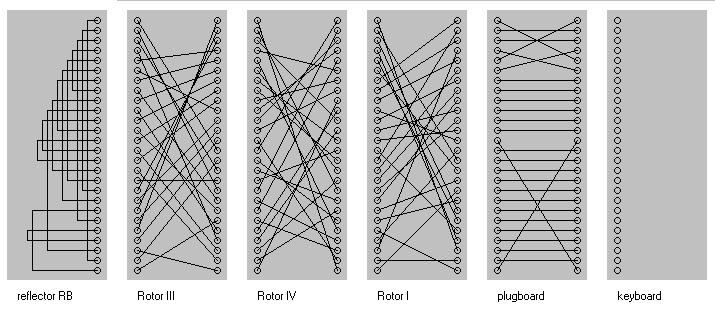
The following may help to envision the total wiring in the enigma machine. It is taken from Ian Noble's Enigma applet. This is an example using rotors 3,4 and 1, and with three plugboard swapping. Press Here for diagram (57K)
I am simplifying things a little, but the basic way Enigma was used was to have a monthly code book with contained a daily setting that was used for all messages in each 24 hour period. If just one message could be broken the daily setting would be know which could enable all the other messages that day to be read.
With the level of sophistication highlighted above Enigma should have been unbreakable, but the Germans had a number of procedural flaws which allowed the British (and the Polish before them) to break the cipher. Some of these were plain stupid, like reusing the monthly code book settings, but the others were less obvious and this is where the Bombe was used. It was discovered that the German military messages were very stereotyped in their nature, and, once decrypted, very careful records were kept regarding how messages on any one communications network tended to look. Typically a message would start something like "To General Bloggo", only it would be all in uppercase letters with out spaces so it would look more like "TOGENERALBLOGGO". This sort of sequence was called a crib (and would of course have been in German). Many other clues were used to get to this position, but when the British thought they had a likely crib they would use the Bombe to reduce the many trillions of possible Enigma settings to a small enough number that they could be individually tested.
The design of this machine and how it was used is generally credited to two brilliant British mathematicians: Alan Turing, and Gordon Welchman. Turing was the first of the two to be involved and saw that with certain cribs there were logical circularities that would rule out all but a few Enigma settings. These were based on the way certain letters were paired together in the plain and cipher texts. If for instance the crib was "TOGENERALBLOGGO" and the ciphered text was "IEDYVTGFYDOJOPT" the letters from these two texts can be matched together thus:
                        * *    * *
                       TOGENERALBLOGGO
                       IEDYVTGFYDOJOPT
The second pairing is O with E the forth is E with Y the ninth is Y with L and the eleventh L with O. This is called a loop because the sequence begins and ends with the came letter, O in this case. Turing realized that there were only so many possible rotor orders and scrambler sequences that could allow this sort of loop to be produced, and that it was possible to build a machine that could search out these possible rotor sequences.
Just before the war the Polish, realizing they were about to be invaded, handed over to the British all the cryptanalytic work they had done on Enigma. This was far more advanced than anything anyone else has achieved and came as quite a surprise. (Without this head start it is doubtful if the British would have been as successful as they were, being one step ahead of the game was a key factor in their success.) One of the things the Polish had developed was a machine they called a Bomba. This is the Polish word for bomb and was probably so named because of the ticking noise it made. The Polish machine and the British one worked on different algorithms, but mechanically were similar, and this provided Turing with a starting point for his own requirements.
A Bombe was rather like a collection of Enigma machines that were all working together. According to Welchman there were twelve sets of Enigma rotors in the Bombe, but there is also other evidence that larger Bombs existed. After the war all the British Bombes were destroyed, so it is difficult to be sure. (I am told, however, that there is one in the The National Cryptologic Museum of the National Security Agency at Fort George G. Meade, MD, USA.) Nevertheless the above crib would only need four sets of rotors. For Turing's technique to eliminate sufficient possibilities more loops are needed, but let us just follow through the example we have got so far anyway.
The theorem we have formed thus far is based on the loop that exists between the crib and the equivalent cipher text. The mechanism Turing devised to test this was to use a standard mathematical technique called a reductio ad absurdum. For every one of the possible rotor settings (all 26 x 26 x 26 x 60 of them) he would start by assuming that this was the correct setting to encipher the crib and then try to disprove this. If the procedure did disprove the setting then the machine would automatically advance to the next setting to be tested. If it did not the setting was recorded, and then the procedure also continued to try and find other possible settings.
Let us follow this through, but start by making a hypothesis that there is no Steckerboard substitution for the letter O. So in this case mathematically we might state:
Stecker(O) = O
If this is true then the input character into the Enigma scrambler in the second position of our crib is O. This goes through the scrambler and returns as another letter which must (according to the theorem we are trying to disprove) be the character Stecker(E). To see this one must recall that because the signal must pass through the Steckerboard before getting to the lampboard the only way that E could appear in the cipher text is because the output of the scrambler was such that the transforming effect of the Steckerboard caused the E signal to be active. The Stecherboard works the same way in both directions, so the letter (or should one say virtual letter) must be Stecker(E).
Because the Steckerboard is never changed after it
is initially set up we also know that the E that was enciphered
in the forth position of the crib must have had
the same Stecker value as the output of the second position.
It is not possible to know what this was (yet) but it is enough
to know only that it must be the same Stecker(E) value.
Moving on in just the same way this must have been translated
by the scrambler (in the forth position) to the character Stecker(Y) .
This is taken to the ninth position in our crib-cipher
paring. Here the sequence is the other way around, L was
enciphered to Y which is the opposite way around to the
way we want for the sequence in the loop. This, however, does
not matter at all, because we know that with the Enigma machine
in any one setting the input and output are reciprocal. If we
typed an L we would get a Y, and had we typed a
Y an L would have appeared (in this example). So
by the same process as before we can think of the output (rather
than the input) of the ninth position being the
character Stecker(L) which
is the input to the eleventh position. Now we come
full circle as the output of the scrambler in this position will
be Stecker(O) which,
if our initial hypothesis, is correct will be O.
Here we are testing our crib theorem using one known character O and three virtual characters Stecker(E), Stecker(Y), and Stecker(L) . The beauty of this is that our theorem can be tested without reference to the actual Steckerboard settings, because no Steckerboard transformations (other then O) are used for the test, and hence the trillions of possible encipherings from this device are of no consequence and only the 26 x 26 x 26 x 60 possible rotor settings need to be tested. This is a number too large for manual testing, but not for a machine.
The question must be asked what if the O letter was transformed by the Steckerboard. We will see later that a very neat consequence of the Bombe's construction was able to address this case.
The elements of the Bombe mirrored just the scrambler portion of this list:
An important difference existed in how the rotors were wired. Turing needed what was called a double scrambler where there were logically two fast, medium, and slow rotors with a reflector in the middle.
               -  -  -  -  -  -  -
              |F||M||S||R||S||M||F|
              |a||e||l||e||l||e||a|
              |s||d||o||f||o||d||s|
              |t||i||w||l||w||i||t|
            / | ||u|| ||e|| ||u|| | \
Output Bus  - | ||m|| ||f|| ||m|| | - Input Bus
            \ | || || ||l|| || || | /
              |R||R||R||e||R||R||R|
              |o||o||o||c||o||o||o|
              |t||t||t||t||t||t||t|
              |o||o||o||o||o||o||o|
              |r||r||r||r||r||r||r|
               -  -  -  -  -  -  -
Here the signals originate from the right, as before, but pass through the seven transformation elements once only from right to left. Physically this was built using only three disks that were placed next to each other on a separate spindles and mounted flat against a mounting board. Each disk had four sets of 26 contacts placed on concentric rings that made electrical contact with a similar set of four rings of 26 contacts on the mounting board. These concentric rings of contacts were used in pairs, the outer two rings performed the right to left rotor transformations, and the inner two the left to right transformations. The connections from rotor to rotor were made in the mounting board, and the reflector mapping was present in the wiring where the contacts of the outer pair of contact rings for the slow rotor disk were wired to its inner two contact rings. Each Bombe had twelve groups of three rotors disks, and each of these groups had separate input and output buses of 26 wires that could be plugged together in different ways.
Leaving aside the physical arraignment of the double scramblers let us think again of the stack of seven transformation elements with the input and output and use the following symbol to represent this:
         |+|
Output - |+| - Input
         |+|
The terms input and output bus will shortly lose their meanings. It should be noted that if, for instance, current to, let us say, the O wire on the left hand bus were transformed to a Y on the right, then if the O wire had current applied to right hand bus the Y on the left hand bus would be made active.
In order to test the crib the scrambler busses would be plugged together to try and disprove the loop which, in the above example, is O-E-Y-L-O. The phase of the scramblers is critical. The Bombe would operate rather like a number of Enigma machines operating in parallel each simultaneously enciphering a different part of the crib. The wiring for the above example would look like this:
      2                  4                  9                 11
     |+|                |+|                |+|                |+|
   - |+| - Stecker(E) - |+| - Stecker(Y) - |+| - Stecker(L) - |+| -
  |  |+|      bus       |+|      bus       |+|      bus       |+|  |
  |                                                                |
   ---------------------------- O bus -----------------------------
                                               |
                                        Test Register
The O bus was connected to a device called the test register which would examine all 26 wires on the bus and stop the Bombe when certain conditions existed. Prior to starting the Bombe the scramblers would have to be set up in the correct phase for the letter pairing of the crib, so in this case the first one would be set to AAB, the next to AAD, the third to AAI and the last AAK. To make the Stecker(O) = O hypothesis the O wire on the O bus would have current applied to it. If after this was done some other wire on the O bus also had current then the rotor settings could not be the correct ones for the loop and the next setting would be tried. The Bombe would advance the fast rotors of all the scramblers so that they were now set to AAC, AAE, AAJ, and AAL. The same test of the O bus would then be made and again if current was present on one of the other wires of the O bus then the rotors were advanced to the next position. When the fast rotor disk had gone around one full circle the middle wheel would be advanced as in turn the fast wheel was thus allowing all 26 x 26 x 26 combinations to be tested. If a particular rotor combination proved only to have the O wire set then the Bombe would stop. The operator would note the position of the Bombe, and allow it to continue with the next combination. This event was known as a "drop".
Not all drops were valid, and the number of invalid drops was proportional to the simplicity of the crib. The above example would have produced an impractical number of false drops so in reality three or four loops would be needed in the crib resulting in a scrambler network that might have looked more like this:
                                |+|                |+|
                --------------- |+| -------------- |+| ------------
               |                |+|        |       |+|             |
               |                           |                       |
     |+|       |        |+|                |   |+|                 |
   - |+| -------------- |+| --------        -- |+| --              |
  |  |+|                |+|         |          |+|   |             |
  |                                 |                |             |
  |                                 |                |             |
  |  |+|                |+|         |      |+|       |        |+|  |
  |- |+| -------------- |+| -------------- |+| -------------- |+| -|
  |  |+|                |+|                |+|                |+|  |
  |                                                                |
  |                                                                |
   ----------------------------------------------------------------
                                               |
                                        Test Register
In such a network (where the loops kept feeding back into each other) when a test was made using an incorrect rotor combination it was very common for all the wires in the test register to end to carrying current. If, as before, the test register was connected to the O bus with current initially being applied to the O wire and all but one of the elements in the test register ended up carrying current this would indicate a very special situation. If, for example, the X wire was the only one not carrying current this would mean that the Bombe might have reached a valid Enigma setting, but one where the O and X letters would have to had been Steckered together.
To see this one can imagine the case where we had started with the hypothesis that Stecker(O) = X. To test this we would have applied current to the X wire on the O bus, and if this had been tested with the correct rotor combination only the X wire in the test register could have been active. The converse therefore is that if, in this situation, current is applied to a different wire on the O bus and it gets to all but the X wire then the rotors must be in a combination where the X wire is electrically isolated implying that O and X were Steckered together.
Finding cribs with three or more loops is not easy, and at this stage Gordon Welchman made an extremely important observation that greatly increased the power of the Bombe, and at the same time reduced its dependence on loops.
      2                  4                  9                 11
     |+|                |+|                |+|                |+|
   - |+| - Stecker(E) - |+| - Stecker(Y) - |+| - Stecker(L) - |+| -
  |  |+|      bus       |+|      bus       |+|      bus       |+|  |
  |                                                                |
   ---------------------------- O bus -----------------------------
                                               |
                                        Test Register
Welchman realized that if when the O wire was translated by the scrambler in position 2 to, let us say, T, with the correct rotor settings, this would mean that Stecker(E) = T, but it would also imply that Stecker(T) = E, and when this was so it could be used to form a further loop.
In this example where we have reached the situation that Stecker(E) = T if we were to augment our network with another scrambler that represented the sixth position of our crib and applied current to the E wire on the Stecker(T) bus the network would now look like this:
              6
             |+|
Stecker(T) - |+| -
bus with E   |+|  |
                  |
          2       |          4                  9                 11
         |+|      |         |+|                |+|                |+|
       - |+| - Stecker(E) - |+| - Stecker(Y) - |+| - Stecker(L) - |+| -
      |  |+|   bus with T   |+|      bus       |+|      bus       |+|  |
      |                                                                |
       ---------------------------- O bus -----------------------------
                                               |
                                        Test Register
The advantage of this is that it will remove some of the false drops, but it can only done when the Stecker(E) = T condition is true. Welchman saw a simple addition to Turing's design could be made that would cause an extra test such as this to be performed, but only when the condition was valid. This extra device was known as the diagonal board and consisted of a square matrix of 26 x 26 terminals. Each row of this matrix corresponded to the Stecker buses A to Z. Not all would be used at one time, but the wiring of the diagonal board was permanently set so that, for example the A wire of the B bus was connected to the B wire of the A bus, A wire of the C bus was connected to the C wire of the A bus, and so the T wire of the E bus was connected to the E wire of the T bus.
When Welchman came up with this enhancement the Bombes being built were immediately changed and the diagonal board became the focal point for the scrambler wiring. All the scrambler connections were connected to relevant bus on the diagonal board thus maximizing the number of extra loops that may be formed. In the above example a T on any of the busses would cause a wire on the Stecker(T) bus to become active.
This modification had two effects. The cribs did not have to contain loops, and they could be shorter. The latter was particularly important because of how the rotors in the Bombe were moved. As far as I can gather the Bombe had 36 rotors that formed 12 sets of 3., so there was a total of 12 fast rotors, 12 medium rotors, and 12 slow rotors. All of the fast rotors were driven together, and when they had gone around one revolution all the medium rotors were advanced to their next position, and when they had gone around all the slow rotors were advanced, so all 17576 rotor positions were tested. This is not how the Enigma machine operated having a basic cycle of 16900 positions, but because the ring settings were not known it was impossible to exclude the appropriate 676 unused positions. Worse than this, it was not possible to know, or predict, if (and where) the middle and slow rotors moved in the cipher text being tested. The normal solution to this was to chop the crib into two halves. One of two halves should be free of middle and fast rotor movement. Without the diagonal board this would have been much harder to do.
In order to clarify how the Bombe worked I wrote a small simulator in C. It is actually a Bombe generator because it works out the Bombe setting from the plain and cipher texts and then produces a C program for that Bombe. This is then compiled and run. Therefore a working C compiler is a requirement for its use.
This program differs from the real Bombe in the following ways:
Unlike the real Bombe the speed of operation of the simulator is dependant on the complexity of the crib, but in general it takes about 8 minutes on a 100Mhz Pentium when the program is correctly optimized. In contrast the real Bombe would have taken something like 15 hours.
The simulator may be downloaded from here
The same program is also available as a Java applet.
|
Back to Frode’s CryptoCellar
|
Site visitors: |